The M8 for Infrared Photography
Introduction
The Leica M8 was introduced in 2007 and was the first digital M camera on the market. I still remember all the discussion before that introduction about the feasibility of a digital M-Leica. People were concerned about the small space between the lens and the film (and later the sensor). As the M cameras are rangefinder cameras, there is no need to engineer the lenses around the mirror housing and therefore wide angle lenses will be constructed to come very close to the film or sensor. Such, the lens itself doesn’t stop at the bayonet but sticks into the camera body. Light rays are such introduced onto the film and sensor in a very shallow angle, which would cause reflections on a normal sensor; film seems to be much less vulnerable to reflections from its surfaces. However, Leica (in cooperation with Kodak) succeeded construction a sensor with shifted microlenses which allow to also capture those rays which are introduced onto the sensor in shallow angles, i.e. those off-centred.
But when the M8 was introduced, another problem became obvious. For whatever reason, Leica had to design the IR blocking filter in front of the sensor in such a way, that it does not effectively enough block the near IR radiation (700-1400nm) from the sensor. In this wavelength range, the sensor is still very sensitive and not blocking this part of the spectrum will introduce colour shifts in the pictures. The effect on the M8 isn’t that bad, and one probably wouldn’t notice on landscape photographs without having a reference image. On pictures of black textiles, the effect becomes easily visible (see pictures below).
Leica didn’t react immediately and left the customers to find all the details of this design flaw. But as reports became numerous, they had to react and finally decided to offer two free IR block filters to be mounted onto the lens for each M8 purchase. This doesn’t sound like a very professional solution and more like a patch work. However, these filters are very effective and actually do give the images the look they should have; the near infrared is effectively blocked (see examples below). The filters do not have to come from Leica, other manufacturers also offer IR block filters (some in combination with UV block effect). One of them is B+W; they offer the 486 filter, which is an interference filter. This means, that the filter effect is slightly dependent on the angle of incidence and therefore it should not be used for picture angles above 60°, which is equal to a 35mm lens on a full frame sensor or a 24mm lns on the M8 sensor (crop factor 1.3). The filter curve of the 486 filter is shown below; as you can see, the transmission is above 80% between 400nm and 670nm. The near infrared spectrum above 700 is very effectively blocked, above 720nm there is less than 10% transmission.


The pictures below show the effect of using a screw on infrared blocking filter. Even though black textiles look black to the human eye, they appear slightly red in the M8 pictures. The infrared spectrum also influences the white balance of the camera. The screw on IR block filter solves all these problems.


As mentioned in the text above, the IR effect is not that easily visible in landscape photographs and one wouldn’t probably notice without a reference image. However, the effect is there and cannot be corrected easily in post processing.


The advantages of rangefinder cameras
As the additional screw on filter required for traditional photography seems to be cumbersome, it is a great possibility for infrared photography. For this kind of photography, only or mostly the extended spectrum into the infrared is used (the near infrared as mentioned above). This is realised by using a filter, which blocks the visible light spectrum (well, the whole spectrum which is visible to the human eye is actually called light…) and transmits the near infrared radiation. These IR filters could also be used on other digital cameras. But as other digital cameras have a very good IR blocking filter in front of the sensor, very long exposure times are required to get some IR radiation onto the sensor. Handheld IR photography is therefore not possible and a tripod has to be used. The M8 infrared filter on the other hand transmits a lot of near IR spectrum and is perfect for IR photography (it could be even ‘more’ perfect if this sensor filter wouldn’t block the IR radiation at all).


Another advantage of the M8 is the rangefinder construction. With a rangefinder camera, the photographer does not look through the lens itself but through an external viewfinder. This might be a draw back because of parallaxes effects. But for infrared photography this is ideal. The view is not affected by any filter in front of the lens. A medium IR filter would still give you a dark red image on a SLR (Single Lens Reflex camera), but a very effective IR filter would leave the image pure black, unusable to arrange your picture. The SLR photographer would therefore need to screw on and off the filter for selecting the frame and shooting; again, a tripod is a must. This is actually also valid for SLRs with modified IR filter in front of the sensor. Even though the sensor is now nicely sensitive to the near infrared, one still needs to screw the IR filter on and off. A solution could be to use an external viewfinder, but then you have to be very careful on using the right viewfinder with the right lens. With a rangefinder camera all this is not required.

Focusing
The refraction index is dependent on the wavelength of the radiation. Electromagnetic waves with a shorter wavelength (higher frequency) will have a higher refracting angle as waves with longer wavelength (lower frequency). Such, near infrared with its longer wavelength than visible light is less affected by the refractive index and therefore focusing has to be corrected accordingly. The focusing apparatus of the M8 is calibrated for the visible spectrum and a constant correction factor has to be applied. This correction factor needs to be found for each lens. You simply take multiple shots of an object a certain distance from you camera (>10m) with your IR filter screwed on. You could use the field of depth markings on the lens for reference. Remember the correct focusing for the visible spectrum and then shift the focus step by step to the right, i.e. the first picture at the correct focusing for visible light, then with that distance shifted to the next depth of field marking to the right (in the picture below this is the marking for f2, and so on.) You then select the picture with the highest sharpness. You could repeat this test with a finer focusing step between the pictures around the correction factor found in the first series. For my Summicron 35mm/f2 I found that the marking for aperture 2 works fine (which is the 1st marking to the right without a number) for the B+W 092 Filter and the marking for the aperture 5.6 (which is the 4th marking to the right) for the B+W filter 093. To take an infrared shot I now first normally focus through the rangefinder, read the distance on the lens and shift it to the the right: that’s it. The pictures below show this for an object at infinity.


To find the exact positions like explained above, I took pictures at several distances and used fine index marker strip attached to the lens with lines every mm like shown in the picture below. I then took a picture for every mm shift to the right and evaluated the maximum sharpness at the appropriate shift. The pictures taken are shown below.
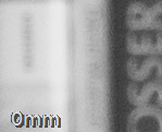
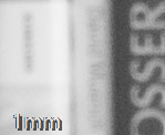
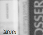
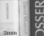
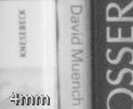
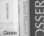
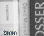
For the filter B+W 093 a focus shift to the right of 4-5mm is adequat, which is approximately the depth of field marking for aperture 5.6.
For the filter B+W 092 a focus shift to the right of approximately 2mm is adequat, which is equal to the depth of field marking for aperture 2.0.


If you think that this procedure of shifting the focus for every exposure is too cumbersome and you would like to have an easier approach to start with, using the hyperfocal distance could be a solution. This distance, which is dependent on the focal length and the aperture value, gives you a depth of field which extends from half the width of the hyperfocal distance to infinity. This approach will not let you play with the focus creatively but its easy to use: Focus once and then just shoot.
The hyperfocal distance is calculated using the following formula:
![]()
H: hyperfocal distance
f: focal length of the lens used (the real focal length and not the one with the crop factor applied)
N: aperture
c: diameter of the circle of confusion, coc
The diameter of the circle of confusion (coc) is 0.03mm for film, which is about equal to the 1500th of the diameter of the film format (the 35mm film in this case). This is based on calculations based on the impression of an enlargement from a conventional 35mm film. With a digital camera, the maximum enlargement can be higher dependent on the amount of pixel (let’s not consider the lens here) and therefore the distance between the pixels can be used as the diameter of the coc (if you assume that there is no gap between the pixel the distance between the pixles and the pixel width is the same). However, this only makes sense, if the sensor is the limitiung factor in the whole optical system, which is not the case if the coc gets smaller than 0.01mm. The lens will not be able to generate such a small coc and therefore it is useless to calculate with this value. In addition to that, in infrared photography, only the red pixels are exposed as all the others don't get illuminated as the IR filter blocks all the visible light from them. This can also be seen looking at the histograms shown below. And the red pixels are only 25% of all pixels as shown below, i.e. the distance of the red pixels is twice the standard pixel distance, i.e. 2x6.8um=13.6um for the M8.

Alternatively, the same calculation base as for the film coc can be taken. In this case, the crop factor of the M8 should be taken into account, which is 1.3. This calculation, which is found widely on the internet, does only makes sense, if the pixels are smaller than 30um on a full frame sensor or smaller than 23um and 19um on a sensor with crop factor 1.3 and 1.6 respectively. This is the case for almost all todays sensors. The coc of 0.03mm is actually not based on the film resolution itself but on an adequate observing distance of pictures of 25cm and a viewing angle of 60° resulting in a picture size of a diameter of 30cm resulting in an enlargement factor of 7 for 35mm fim. And based on the fact that the human eye can resolve about 5 linepairs per mm at 25cm distance which is equivalent to a coc of 0.2mm, the coc on the 35mm film needs to be 7 times smaller, which is equal to 0.03mm.
The three tables below are based on the three values mentioned in the text above. The tables are valid for the 10MPixle Sensor of the M8 with a 1.3 crop factor:


Using the hyperfocal distance for infrared photography is now quite simple. You select an aperture you would like to take pictures with, let’s say aperture 8 on a 35mm lens. The table above tells you, that the hyperfocal distance for that combination is 11m (in the lowest table). This means, that all objects between 5.5m and infinity are rendered sharp on the picture. You still need to shift the distance with the offset found above for infrared photography, i.e. shift the 11m one or four marks to the right depending on the filter used as explained above.


Exposure
It is amazing: the exposure meter of the M8 is also useable for infrared photography. You still need to apply certain correction factors for various light situations as in traditional photography. And you should use the ‘expose to the right’ rules, as in traditional photography. Using this technique, you will choose the exposure that will generate a histogram which is shifted to the right as much as possible without being cut off at the right hand side.

Some cameras will give you a certain headroom when using the RAW format, which means that you can even overexpose the picture a little bit, lets say by half a stop or even one full stop, which will give a histogram which is chopped off at the right hand side. I am using this on my Canon 5DMark2 and I think I have 0.5-1 stop headroom: the overexposed regions can later be regenerated using the highlight recovery slider in Lightroom (or similar sliders in other RAW converters). The M8s headroom is very narrow and it took me some time to get used to this behaviour, as I was used to overexpose a little with the Canon. Using this on the M8 will give you some ugly looking highlights which cannot be recovered in the RAW processor. The reason might be that the M8 uses a CCD sensor and not a CMOS as the Canon, but I am not aware of the details.
For Infrared photography it is also important to use the histogram for the three sensor colours, i.e. the RGB histogram rather than the luminance histogram. As here all the information is packed into the red channel, the luminance histogram doesn’t give you the correct information as for this histogram all three channels are averaged which would lead to an incorrect exposure.
I shall mention here that using the ‘expose to the right’ approach, one would expose objects with low contrast longer than those in the same light with higher contrast. You do all this to make optimal use of the dynamic range of your sensor and to circumvent noise in the shadows, as the shadows are rendered with less exposure steps as the light regions.


I use the following approach: First of all I use the exposure meter of the M8 to find an exposure. I use this and make a test image which I will use to evaluate the histogram. If it is not correct from the beginning, I can now calculate the offset and use the manual exposure setting with the correction factor found. After the second image I check again the histogram. If it is OK, I use this exposure setting for the following pictures until the exposure needs further corrections. I think this is easier to use than the exposure offset to be dialed on for every exposure via the back panel display. The picture on the display will show a red appearance dependent on the filter you use. This is shown in the pictures above for two different filters. But as the picture is later converted into a black and white picture this is not important at all. The filters with the higher blocking in the visible spectrum will give a more neutral look on the display, which may be easier for evaluation purposes than the dark red coloured pictures from other filters.

Filters
The graph and the picture below show different IR filters with different blocking rates for the visible spectrum. The filter 099 from B+W still transmits a lot of the visible spectrum while the 092 filter blocks much more of it. The 093 filter is the one filtering out all visible light and appears to be totally black, while looking through the 092 will give you a very dark red picture (sometimes the eye first needs to get adapted to this dark picture to see anything at all). While you could still use the 092 filter with normal ISO ratings, the ones required for the 093 filter and handheld shots are relatively high. This is due to the fact that the M8 IR block-filter in front of the sensor transmits less IR at longer wavelengths than at shorter ones.


Typical IR effects are deep black skies (which is very nice to capture clouds) and the light rendering of all green vegetation. The green leaves from trees seem to reflect a lot of near infrared radiation and therefore appear very light in the final picture which gives a dreamy appearance. Both effects are exaggerated with the 093 filter compared to the 092 filter, which will give a more natural look. The pictures below show the same pictures taken with the 486 filter and then with the 092 and the 093 filter screwed on.


Another typical IR photography effect is the reduced scattering in the atmosphere. Scattering is dependent on the relative size of the objects to the wavelength. Typical examples are the blue sky (short wavelengths are scattered more than longer ones as the particles in the atmosphere are closer in size to the blue wavelength) and the red sunset. As the short wavelengths are scattered away during the lights travel through the atmosphere, the radiation in a narrow angle around the sun looks reddish. The infrared radiation has even longer wavelength and is less scattered. A view from a high mountain will always be influenced by the scattering effect of the atmosphere. Objects which lay further away from the viewer appear bluish. On an infrared image on the other hand, the objects are clearly visible, as the IR rays are less scattered. The same applies for pictures taking out of a plane as shown below.


